Inverter and VFD Basics: Controlling Motor Speed
Learn how inverters and VFDs vary motor speed using frequency control, save energy, protect equipment, and improve process performance.
Why Motor Speed Control Matters: Variable speed control turns a fixed-speed electric motor into a flexible workhorse. An inverter paired with a variable frequency drive (VFD) lets you adjust the electrical frequency and voltage supplied to an AC motor, directly shaping its speed and torque. In the category of motors, this means processes become smoother, machines last longer, and energy use often drops significantly. Most industrial AC motors, like induction and permanent magnet types, are built to run at a speed linked to electrical frequency and the number of poles in the stator. By changing frequency, a VFD shifts that operating point without mechanical gears or dampers. Benefits include soft starting to reduce inrush current and mechanical shock, precise speed regulation for quality control, and torque tailoring for demanding loads. Whether driving a pump, fan, conveyor, mixer, or spindle, controlling speed unlocks process optimization. The outcome is greater throughput, gentler handling of equipment, improved safety, and lower lifecycle cost.
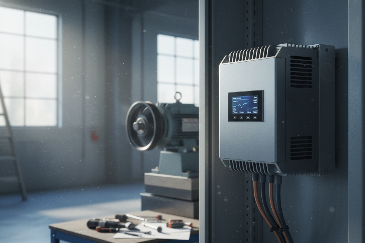
How an Inverter Creates Adjustable Power: A VFD first rectifies AC line power into DC, storing energy on a DC bus with capacitors and sometimes a reactor for smoothing. High-speed switches, typically IGBT or MOSFET devices, then reconstruct a three-phase output using pulse width modulation (PWM). By varying the modulation index and output frequency, the drive creates an effective sinusoidal waveform with controlled amplitude and frequency. Key parameters include carrier frequency, which influences audible noise, heating, and electromagnetic emissions, and voltage boost at low speed to overcome motor impedance and friction. Long motor leads may introduce dv/dt stress and reflected waves, so output reactors or sine filters can protect insulation and reduce EMI. Many drives accept single-phase input yet deliver three-phase motor power, widening application options. The result is a compact, electronic gearbox that steplessly matches motor output to process demands with high efficiency and precise control.
Core Control Methods: VFDs use several strategies to shape torque and speed. The simplest, scalar V over f (V f) control, maintains a proportional relationship between voltage and frequency, providing reliable open-loop operation with moderate speed accuracy. Enhancements like slip compensation help stabilize speed under changing load. For faster response and better low-speed torque, sensorless vector control estimates motor flux and rotor position mathematically, improving regulation without feedback hardware. At the top tier, field-oriented control (FOC) with an encoder or resolver delivers tight speed holding, rapid torque transients, and precise positioning, ideal for demanding motion tasks. Drives often include auto-tuning that measures motor parameters to optimize models used by vector algorithms. Selection depends on your priorities: simplicity and cost favor V f, while dynamic performance and accuracy favor vector or FOC. No matter the method, well-chosen limits, filters, and ramp profiles stabilize operation, minimize mechanical stress, and keep the motor within safe thermal boundaries across a wide speed range.
Matching Drive, Motor, and Load: Successful projects start with a clear view of the load profile. Variable torque applications like fans and centrifugal pumps exhibit torque rising with speed, where small speed reductions yield large energy savings. Constant torque loads such as conveyors, mixers, and extruders need robust low-speed torque and may require heavier-duty ratings. Some systems operate in a constant power region above base speed through field weakening, especially with permanent magnet motors, though available torque will drop. Proper sizing balances continuous current, short-term overload, duty cycle, ambient temperature, enclosure, and cooling. Consider derating for high temperature, altitude, or restricted airflow. If fast deceleration is needed, add dynamic braking with a resistor, or choose a regenerative front end to return energy to the source. Mechanical resonance may demand skip frequencies. Work through the entire speed-torque envelope, including startup and upset conditions, to ensure the chosen VFD and motor deliver reliable service without nuisance trips.
Wiring, Protection, and EMC: Good wiring practice protects equipment and nearby systems. Use proper grounding, short motor leads where possible, and shielded cable to contain EMI. Star-point grounding and attention to termination quality help avoid ground loops and noise. Long cables can cause voltage reflections, high dv/dt, and common-mode currents that stress insulation and bearings; dV dT filters, sine filters, and insulated bearings mitigate these effects. On the line side, input reactors or filters reduce harmonics and protect the DC bus. Built-in protections such as overcurrent, overvoltage, undervoltage, ground fault, and I squared t thermal models guard the motor and drive. Features like stall prevention, flying start for coasting loads, and torque limits enhance resilience. Separate control wiring from power conductors, observe correct shielding practices, and follow enclosure and cooling guidelines. Careful attention to EMC during layout, bonding, and filtering ensures consistent performance in electrically noisy environments.
Commissioning Essentials: Effective startup begins with accurate nameplate entry: rated voltage, current, frequency, base speed, and power. Configure acceleration and deceleration ramps to respect mechanical limits; S-curve profiles reduce shock on belts, couplings, and product. Set current limits to protect the motor while allowing necessary overload for starting. Define skip frequencies to dodge structural resonance peaks. For process control, the internal PID can regulate speed, pressure, flow, or tension using an analog or digital feedback signal. Many drives support multi-speed presets, jog, and logic functions for local sequencing. Choose braking methods such as DC injection for gentle stops or a resistor for rapid decel. Run autotune routines, stationary or rotating, so the controller learns motor resistance, inductance, and inertia. Verify rotation, check no-load current, and confirm temperature rise under typical duty. Document parameters, label wiring, and store backups to streamline future maintenance and replacements.
Operation, Maintenance, and Optimization: Keep systems reliable with routine checks of cooling fans, filters, and heat sinks, since temperature is a primary life driver for power electronics and capacitors. Inspect terminal tightness, cable shields, and grounds to prevent intermittent faults. Use the drive's diagnostics, trend logs, and fault codes to spot rising currents, frequent trips, or abnormal harmonics. If overcurrent trips occur during acceleration, consider extending ramps, reviewing load friction, or increasing torque boost within safe limits. Audible motor noise can often be reduced by adjusting carrier frequency, mindful of thermal impact. For efficiency, enable energy optimization features where appropriate, schedule sleep or stop modes for idle periods, and verify that process setpoints reflect real demand. On the line side, reactors or harmonic filters improve power quality; active front ends add low harmonics and regeneration. Maintain clean enclosures, ensure airflow, and apply safe lockout practices during service. These habits extend component life, stabilize production, and sustain the full benefits of variable speed control.