Motor Efficiency Explained: From Losses to Performance
Demystify motor efficiency: understand losses, performance curves, test standards, and practical design and operating tips to cut energy use and cost.
Understanding Motor Efficiency: Motor efficiency expresses how effectively an electric motor converts electrical input into mechanical output. In simple terms, it is the ratio of output power to input power, where output power equals torque multiplied by speed. What seems straightforward becomes nuanced once you define the system boundary: auxiliary components like cooling fans and control electronics draw power, while gearboxes and couplings add losses downstream. Efficiency is not fixed; it varies with load, speed, temperature, and control method. Most motors exhibit a characteristic efficiency curve with a sweet spot at moderate to high load, tapering at very light or very heavy demand. Distinguish efficiency from power factor: both shape your utility bill and thermal stress, but they are different metrics. Also consider duty cycle and start-stop patterns, which influence average losses and heat rise. By focusing on the full energy pathway—from supply through drive to shaft—you can judge the true, system-level performance rather than relying solely on a nameplate value.
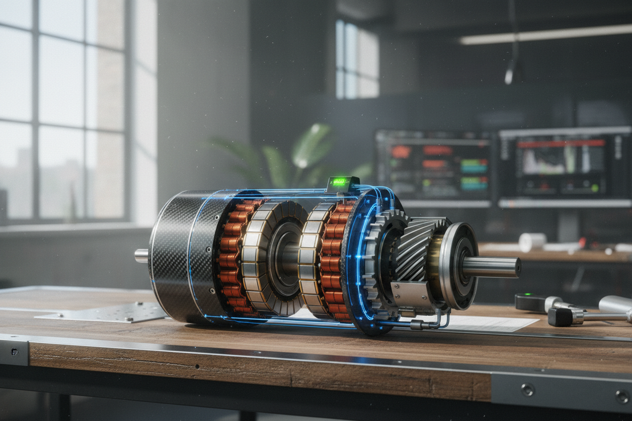
Dissecting Losses: Losses in electric motors fall into a few core buckets. Copper losses (I²R) occur in stator windings and, for induction designs, in the rotor, scaling with current and rising as temperature increases resistance. Core losses combine hysteresis (energy to reverse magnetic domains) and eddy currents (circulating currents in steel), both linked to flux density and electrical frequency. Mechanical losses arise from bearing friction and windage from the cooling fan and rotor drag. Stray load losses stem from leakage flux, slotting, and space harmonics that are hard to model yet measurable. When driven by PWM inverters, additional harmonic content can elevate copper and iron heating, sometimes demanding improved cooling or filtering. Not all unwanted current is a loss: magnetizing current increases line amps and heating but does not directly produce mechanical output. Each loss mechanism has a distinct dependence on speed, load, and thermal state, so understanding their interplay is key to reducing waste.
Design Choices That Boost Efficiency: High efficiency begins with magnetic materials and geometry. Thin, high-grade laminations reduce eddy currents, while optimized tooth and yoke dimensions manage flux density to curb hysteresis losses. In windings, higher slot fill, larger cross-section conductors, and short end turns lower resistance, and careful distribution minimizes leakage and hot spots. Rotor technology matters: induction motors benefit from low-resistance bars and end rings, while permanent-magnet or synchronous reluctance topologies avoid rotor I²R losses altogether. Precision in air-gap control, rotor skewing to reduce torque ripple, and low-loss bearings shrink mechanical dissipation. Thermal design—enhanced cooling paths, fans, or liquid jackets—keeps copper and steel at temperatures where losses are lower. Paired with intelligent variable-speed drives, modern controls can trim magnetizing flux at partial load, improving part-load efficiency. Every upgrade carries trade-offs, from cost and complexity to start-up behavior and rare-earth content, but a balanced design unlocks substantial gains in efficiency and reliability.
Testing, Mapping, and Interpreting Performance: Measuring efficiency rigorously involves both direct and indirect approaches. A classic input–output test uses a dynamometer to capture torque and speed while high-accuracy meters track electrical input; subtracting known losses yields efficiency. Segregated-loss methods estimate components: a no-load test evaluates core and mechanical losses at various voltages, while a locked-rotor test characterizes copper losses and leakage reactance. Temperature stabilization and corrections are essential because resistance and iron behavior shift with heat. For deeper insight, engineers build efficiency maps across torque and speed, revealing optimal operating islands for variable-speed applications. Models, from equivalent circuits to finite element analysis, predict performance and guide design tweaks, but should be validated with calibrated instruments and an uncertainty budget. When using PWM drives, measure with bandwidth-aware sensors to capture harmonics accurately. The result is a trustworthy picture of loss distribution, part-load behavior, and how the motor, drive, and load interact in real conditions.
Operating For Peak Real-World Performance: True efficiency emerges from daily operation. Begin with right-sizing: oversized motors run cool but waste energy at light load, while undersized units overheat and age prematurely. Use variable-frequency drives to match speed to process demand; for pumps and fans, the affinity laws reward even modest speed reductions with outsized power savings. Tune control modes—scalar V/f for simplicity or vector control for high torque accuracy—and manage field weakening at high speed. Minimize transmission losses with proper alignment, well-lubricated bearings, efficient gearboxes, or direct drive where feasible; avoid throttling and dampers that burn energy. Keep cooling paths clean to restrain temperature and copper losses, and monitor vibration, insulation health, and power quality to catch issues early. Track live metrics—input power, power factor, torque, speed, and winding temperature—to verify gains. A disciplined mix of maintenance, controls tuning, and system-level optimization delivers sustained performance, lower operating cost, and longer motor life.